
How To Series by Jake Kavanagh with Wessex Resins and adhesives
The beauty of epoxy is that it makes a tough, non-shrinking connection between various angles of wood, ideal when you want to make a plug for a custom mould. Which is why he wrote this article for us on how to make a oil drip tray.
Not that we don’t trust the brand-new gearbox in our boat but it still needs a drip tray to avoid accidental pollution of the sea via the bilge water. The problem was our home-made ferro cement boat wasn’t exactly symmetrical – so the space beneath the gearbox was full of odd angles and protrusions. Nothing off-the-shelf would fit properly so the answer was to make a fibreglass drip tray that would follow the angles. For that we needed some offcuts of plywood or MDF, some WEST SYSTEM ® 105 Epoxy Resin, 205 Fast Hardener and some 405 Filleting Blend.
The step by step process
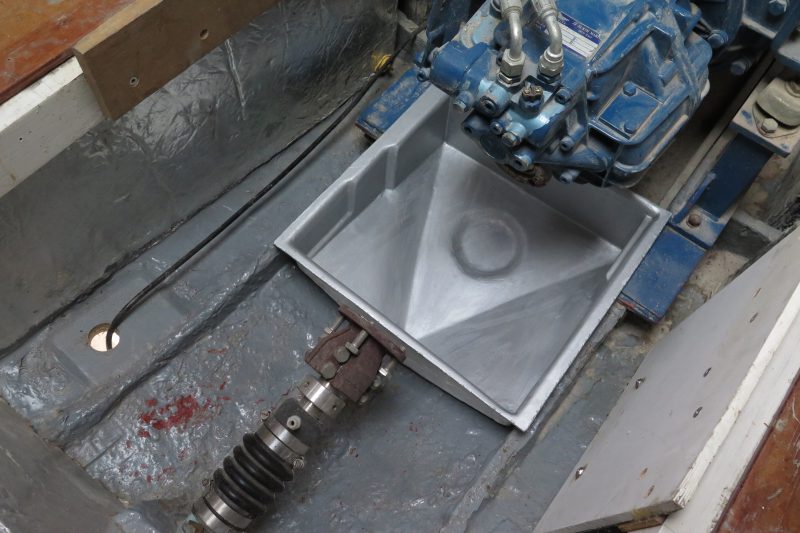
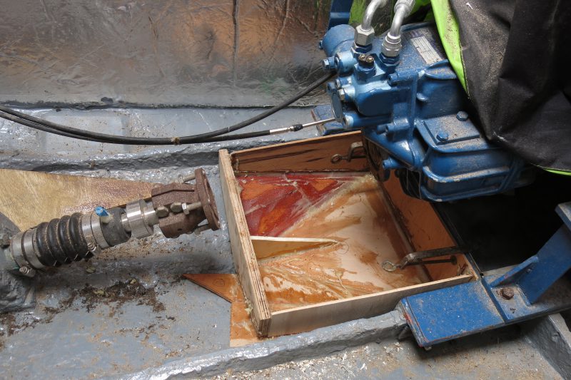
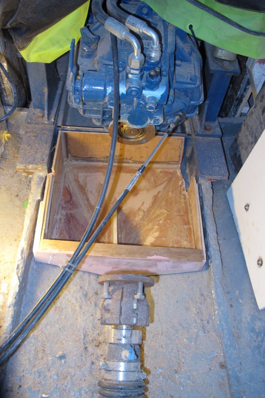
This is the void beneath the gearbox. Any drips of hydraulic oil could contaminate the bilge water, plus a drip tray alerts you to any weeping seals. But the shape is awkward, mainly due to the design of the engine beds.
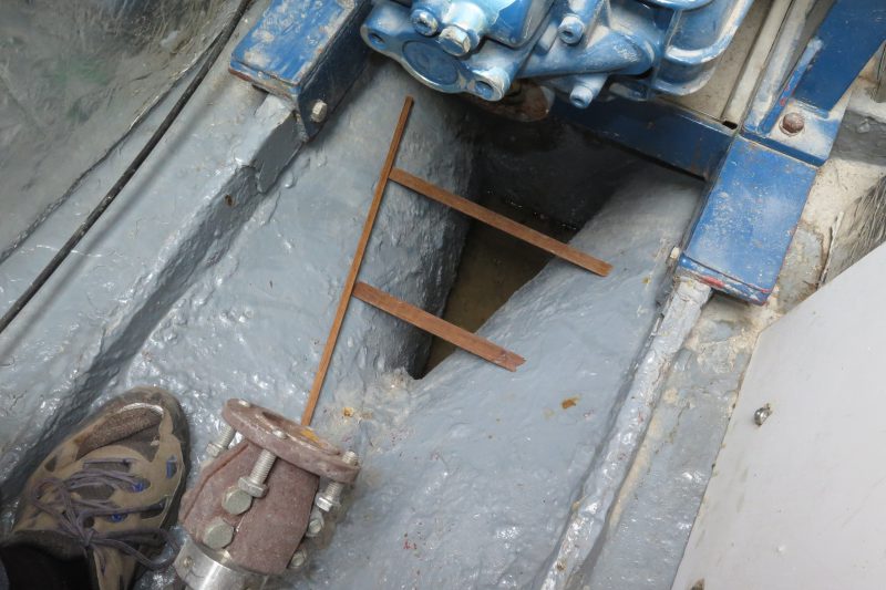
There are several ways to make a template. My favoured method is to use thin strips of wood (bought as bundles of offcuts from my local hardwood specialist). These are snapped roughly to length and then hot glued together to create a ‘cage’ of the right proportions. The dimensions are then transferred into panels. You can also use cardboard shapes cut with scissors.
The basic panels of the box were jigsawn from offcuts of MDF and plywood and then filleted into place. Overlaps underneath each section downwards is fine, as they will be ground back later. The important thing when making a plug is to allow for the 6mm or so that the gelcoat and resin will take up. Note the piece of 6mm plywood projecting from the back of the rough shape to act as a spacer.
Adjustments had to be made to the plug as it was created.
Here a side section (starboard side) has been removed for reworking as it was too tight on the engine bearer.
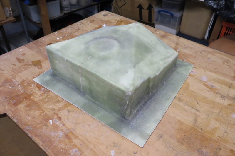
The rough shape is then removed from the bilge, turned over and a sander and grinder used to trim back the overlaps to make a smooth shape. A circular mound to create the depression for a drain was added (for removing cleaning water).
The smoothed off plug was then placed on a flat board and filleted into place. It was given two coats of WEST SYSTEM ® 105 Epoxy Resin with 205 Fast Hardener to stabilise the structure and create a sound layer to build up with filler where needed. WEST SYSTEM 410 Microlight filler, added to the epoxy mix, creates an easily sanded filler ideal for this type of work.
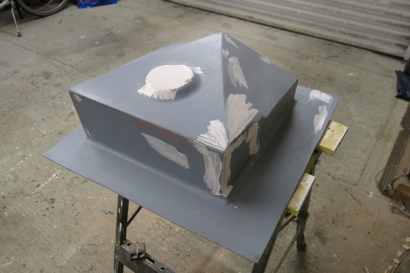
The plug is rinsed with fresh water to remove the amine blush, dried and then given a coat of primer, which usually reveals a few imperfections that need some secondary filler. Once this has cured and been sanded the plug is ready for another coat of primer.
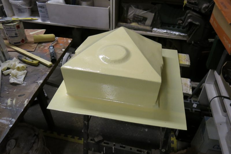
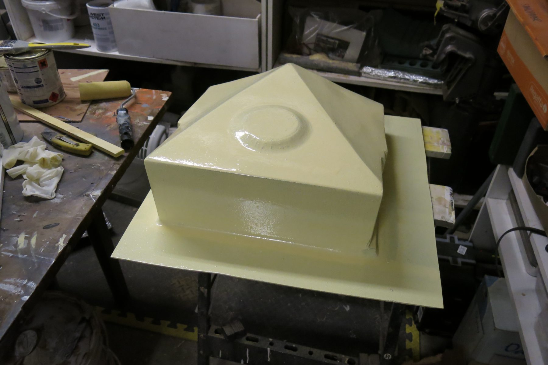
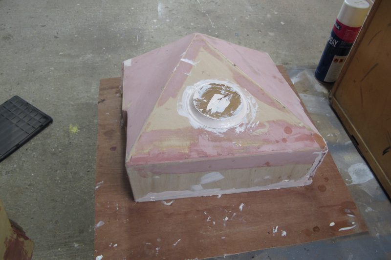
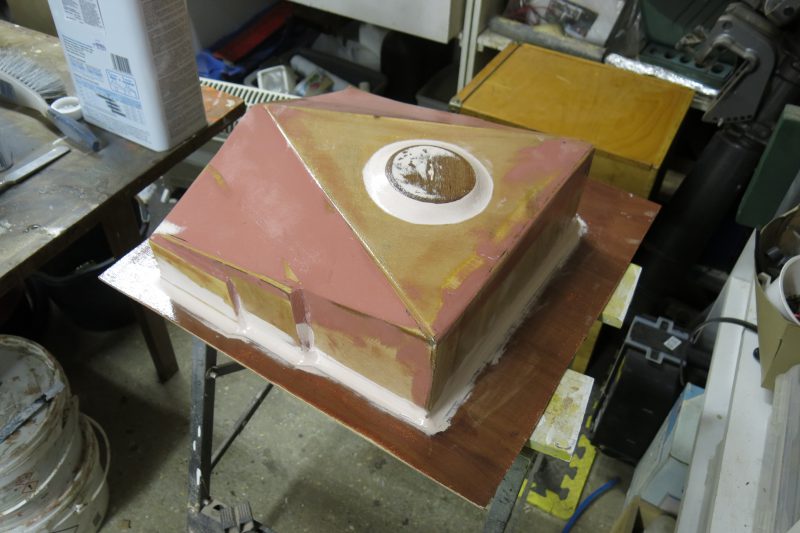
Now the plug is given a couple of top coats of a high-gloss paint. Two pack is usually best, as it forms a really hard surface to mould from, but single pack can also be used. Bear in mind that some paints will leach pigment into your gelcoat. We used this yellow as an undercoat.
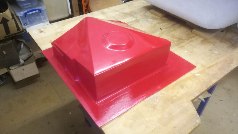
The final plug was painted red in a single pack paint. Using a different base colour to the gelcoat you are applying shows you what has been covered.
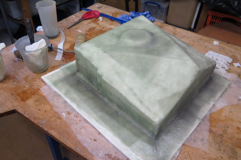
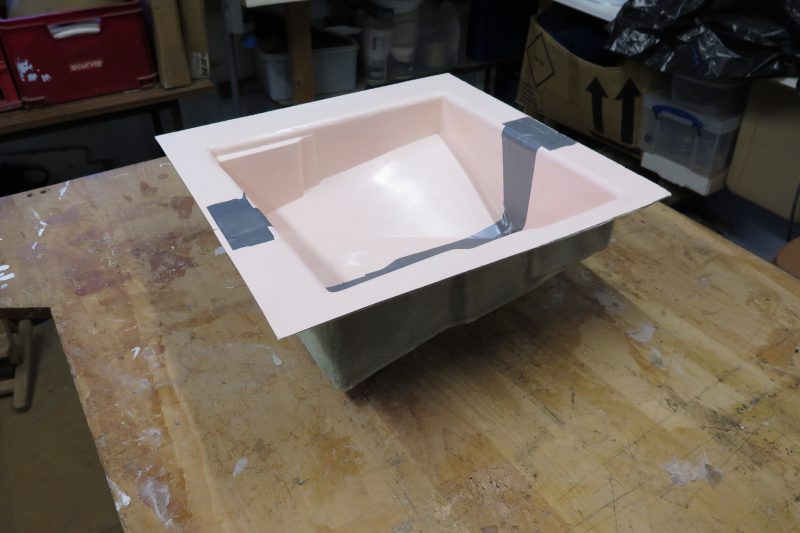
White gelcoat was activated with resin and painted to the thickness of a business card all over the surface and base. Once tacky (squeaky when a finger is drawn across it) the chopped strand mat was applied over the top, wetted out with polyester resin and then rolled down onto the plug.
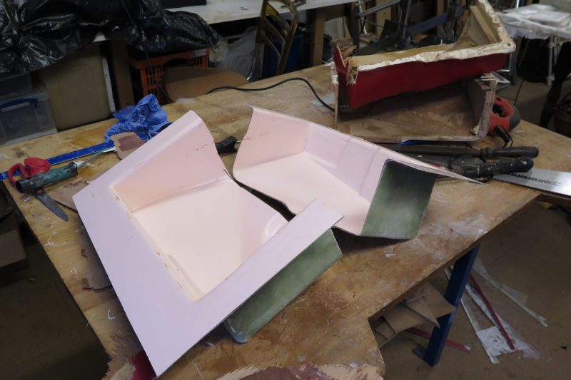
Two mistakes were made but the great thing about working in epoxy is that they were both correctable. The first was that the plug had a reverse angle on it which we hadn’t fully appreciated. This locked the moulding onto the mould. The only way to release it was to cut the entire thing in half. Also, notice the pink hue? Some pigment from the paint leached into the gelcoat. Not a problem – we’re going to paint it again anyway.
To make the repairs, our split moulding was taped on the inside…
..and then inverted again for the two halves to be glassed together with a strip of reinforcement tape.
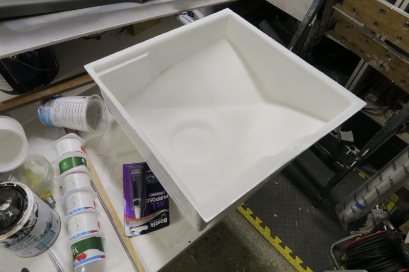
A little epoxy filler into the join and some light sanding caused it to vanish. Then the drip tray was spray-painted with primer.
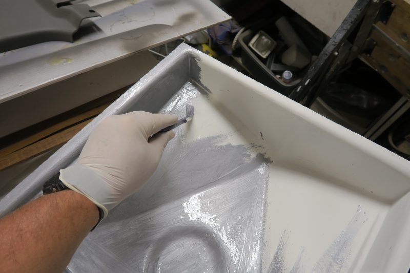
We had a little Hammerite silver paint left over, so used it up as a final coat for the drip tray.
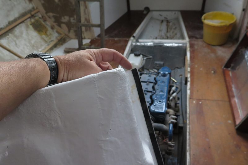
A final touch was to glue some thin foam tape to the underside of the tray where it will contact the engine beds. This will stop any annoying vibration at low revs.

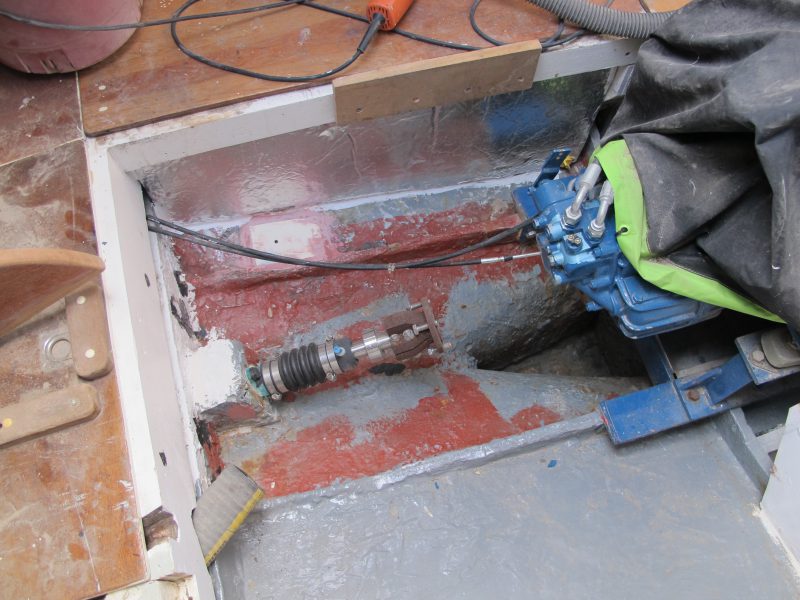
In position. It seems odd to spend a lot of time and effort on a piece of kit that will rarely see the light of day but it was fun to make and the techniques used are good practice for bigger projects. These will eventually include a hatch garage, a chain locker tray and a fuel tank…remembering to avoid reverse cambers on the plug unless the mould is made to be split.